Inductor design procedure is an important to follow for getting the targeted inductance value with a proper functioning and decent efficiency.
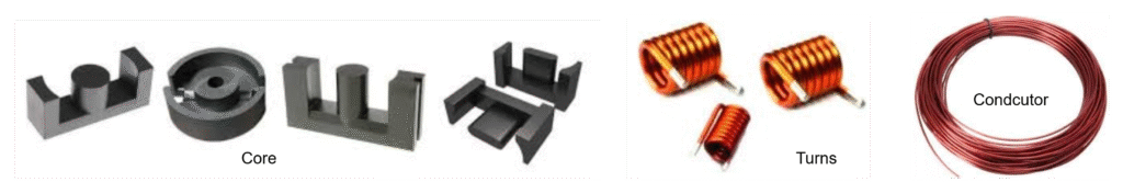
These steps depends mainly on 3 things
- Proper selection of core,
- Calculation of required turns, and
- Proper selection of winding wire.
The complete design steps and flow shown in below flowchart for better understanding.
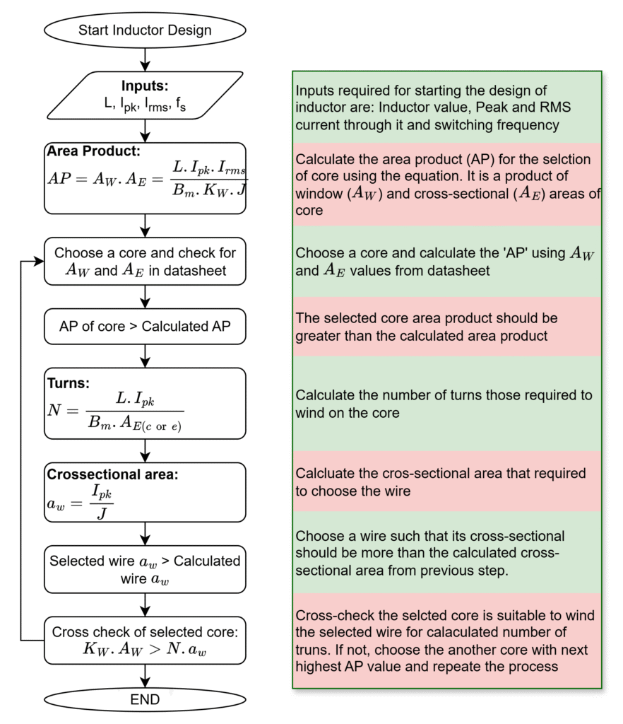
The derivation of area product equation and number of turns equation clearly explained in inductor design equations.
AE – Effective cross-sectional area of core
AW – Core window area
AP – Area product
fs – Frequency
Bm – Peak flux density
Kw – Window space factor
J – Current density
aw – Copper wire winding area
Leave a Reply