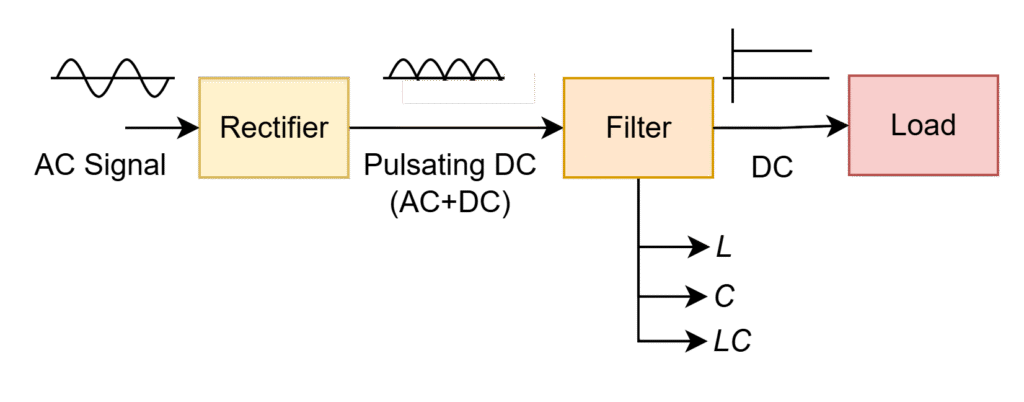
The rectifier is used to convert the AC source to DC source. But in actual, it can produce pulsating DC that means waveform will have both AC and DC components. To get actual DC voltage, we need to use filters those reduce or eliminates the AC quantity and gives only DC quantity to the load. These filters are classified as
- Inductor filter (L)
- Capacitor filter (C)
- Inductor-capacitor filter (LC)
The pictorial view is shown in below Fig.
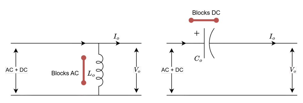
L – Filter
The basic nature of an inductor can see using its impedance equation
XL = 2π.f.L
- When f = 0,
XL = 0 => Acts as short circuit => nothing but it just passes/allows the DC signal through it without any disturbance.
- When f = infinity (∞),
XL = ∞ => Acts as open circuit => Resist/blocks the frequency component i.e. AC signal can not pass through it due to open circuit.
The clear picture of inductor filter operation is given in below figure
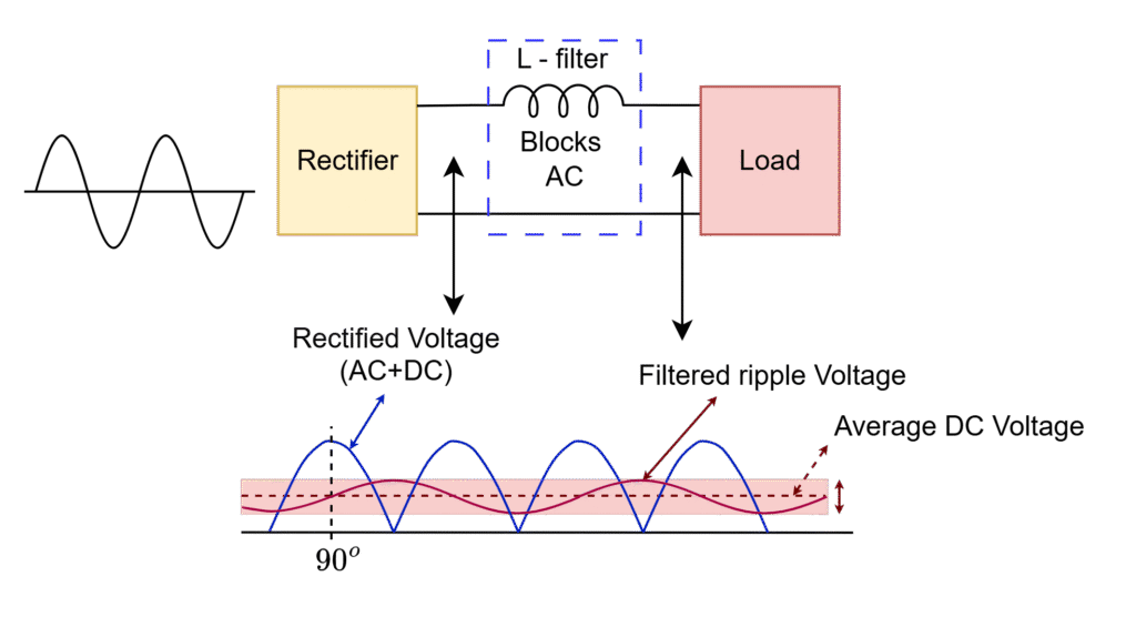
The AC source is applied at rectifier, it converters that into pulsating DC and then it applied to the inductor filter. The DC signal passes through the inductor and reaches the load and the AC signal will not reach/pass the load due to it is blocked/vanished/dropped at the inductor filter.
To drop out this AC signal at L-filter, the condition is XL >> Load resistance i.e., we are making the high-impedance path
The output of the filter is close to the desired DC output but not pure (still it will have some low-frequency AC component in form ripple)
The L-filter is better option for high-load current applications because, the magnetic field creation with high-currents is more. Then inductor filter more effectively blocks the AC component when it is passing through it.
C – Filter
The basic nature of a capacitor also can see using its impedance equation
Xc = 1/(2π.f.C)
- When f = 0,
Xc = ∞ => Acts as open circuit => Resist/blocks the non-frequency component i.e. DC signal can not pass through it due to open circuit.
- When f = ∞,
XL = 0 => Acts as short circuit => Nothing but it just passes/allows the AC signal through it without any disturbance.
The clear picture of capacitor filter operation is given in below figure
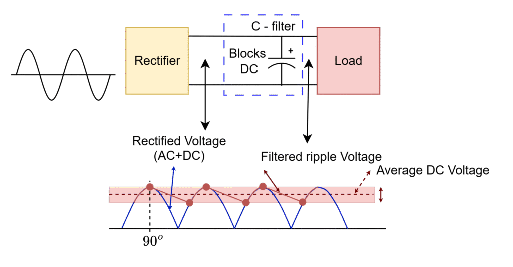
The AC source is applied at rectifier, it converters that into pulsating DC and then it applied to the capacitor filter. The AC signal passes through the capacitor and reaches back the source and the DC signal will be blocked by it and same is appears across the load.
Capacitor starts charging when its stored voltage is less than the rectified voltage, and starts discharging when it has more stored voltage than rectified as shown above fig.
To pass out this AC signal through C-filter, the condition is Xc << Load resistance i.e., we are making the low-impedance path
The output of the filter is close to the desired DC output but not pure (still it will have some low-frequency AC component in form ripple)
The C-filter is better option for low-load current applications because, the charging and discharging times of capacitor is more with the low load current. Then capacitor filter blocks the DC component with less voltage ripple when it is passing through it to provide smooth DC output.
LC – Filter
In reality, only L-filter or only C-filter can not perform the complete job of filtering. Hence, combination of these two filters give better filtering performance to get smooth DC output across load as shown below.
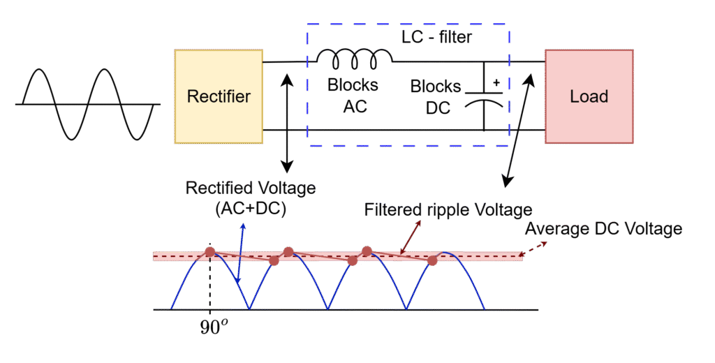
As shown in diagram, the effectiveness of filter increases when combining two individual filters by reducing the peak-to-peak ripple amplitude i.e. smoothing the DC output voltage.
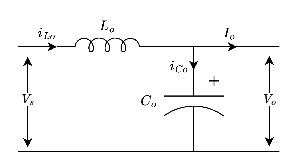
Voltage across an inductor,
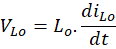
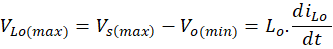
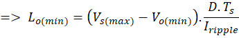
Here,

Current through filter capacitor,
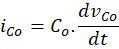
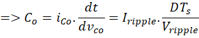
Here,

Why Inductor should be in connected in series while capacitor in parallel?
The L-filter is connected in series why not in parallel: we need to see the DC at the output from the input applied (AC+DC), if we connect inductor filter in parallel, the dc component will pass through the inductor and goes back to input side and blocks the AC component signal. Instead of DC signal at output, AC signal will appear across load. Therefore, L-filter always needs to be connected in series.
The C-filter is connected in parallel why not in series: we need to pass the DC signal from the input applied towards load output, if we connect capacitor filter in series, the dc component will block at the capacitor and never goes to the load, and can not see DC across load and only goes through load. Therefore, C-filter always needs to be connected in parallel.
Leave a Reply