Totem-pole PFC rectifier is widely used topology in single-phase applications for power factor correction.
- Circuit Description
- Circuit Operation
- Circuit Analysis
- Circuit Design
Circuit Description
The totem-pole topologies are shown below. This topology replace the conventional diode bridge rectifier in boost PFC topology with an active high-frequency switches in one leg and low-frequency diodes in another leg.
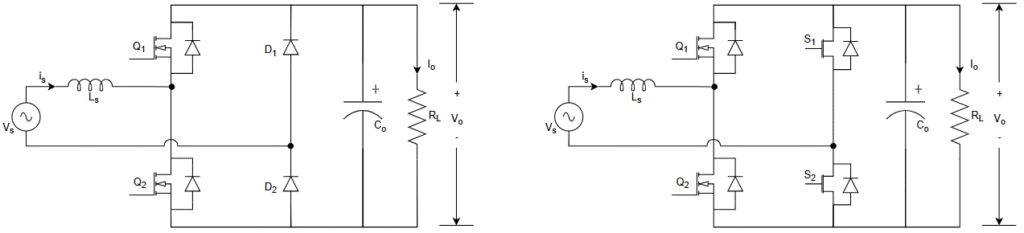
The diode leg can be further replace with low-frequency switches to reduce the conduction losses and further boost the efficiency.
This topology is also called bridgeless topology because it completely eliminated the diode bridge in boost PFC rectifier by replacing it with active switches.
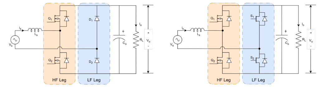
- Leg-1 : fast/high-frequency leg
- Leg-2 : slow/low-frequency leg
Circuit Operation
The operation of totem-pole divided into
- Positive half cycle: positive voltage and current
- Negative half cycle: Negative voltage and current
Voltage and current which are drawn from grid are always in-pahse with same frequency.


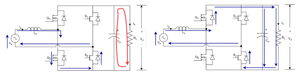
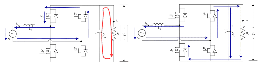
Positive half cycle: positive voltage and current
Current which is drawn in positve half cycle from grid can go in two directions. One is through body diode of Q1 and another is through switch Q2.
- Current can enter through switch Q2 when it is ON and leaves to grid through diode D2 due to forward bias as shown in first figure below. This current does not flow through load. The stored energy in output capacitor discharge througu load resistance, hence output voltage appears.
Voltage across inductor,
VL = Vs
- When Q2 is OFF, current always go through body diode of switch Q1 and flows through load, diode D2 and then grid as shown in second figure below. This current does flow through output capacitor and load. The energy will be stroed in output capacitor and appears across load.
Voltage across inductor,
VL = Vs – Vo
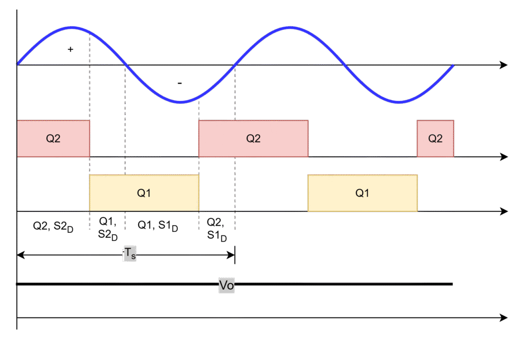
It is observed that D2 always conducts to provide path to positve current in positve half cycle, conduction of body diode of Q1 and switch Q2 alter due to control of turn-on and turn-off periods for the switch Q2.
Q2 ON period: turn-on period of positve half cycle
Q1 ON period: turn-off period of positive half cycle
Negative half cycle: negative voltage and current
Current which is flowing in negative half cycle to grid can flow in two directions. One is through switch Q1 and another is through body diode of Q2.
- Current can enter through switch Q1 when it is ON and leaves to grid to flow through diode D1 due to forward bias as shown in first figure below. This current does not flow through load. The stored energy in output capacitor discharge througu load resistance, hence output voltage appears.
Voltage across inductor,
VL = Vs
- When Q1 is OFF, current always go through body diode of switch Q2 and flows through grid, diode D1 and then load as shown in second figure below. This current does flow through output capacitor and load. The energy will be stroed in output capacitor and appears across load.
Voltage across inductor,
VL = Vs + Vo
It is observed that D1 always conducts to provide path to current in negative half cycle, conduction of body diode of Q2 and switch Q1 alter due to control of turn-on and turn-off periods for the switch Q1.
Q1 ON period: turn-on period of negative half cycle
Q2 ON period: turn-off period of negative half cycle.
The analysis and design of above discussed totem-pole circuit is discussed here.
Leave a Reply