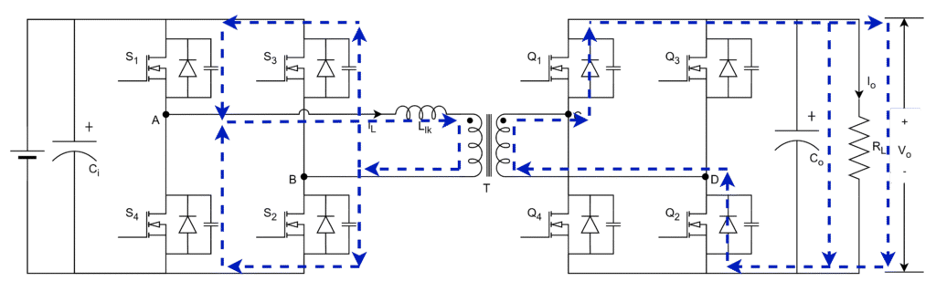
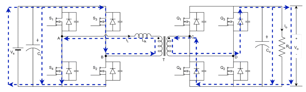
The operating principle of single phase-shift control for dual active bridge converter is explained. The switching sequence of DAB converter is divided into 10 intervals based on the
- Inductor current waveform
- Phase-shift between the primary and secondary bridge voltages
- Dead-time between the leg switches.
Interval-1 (0 – t1)
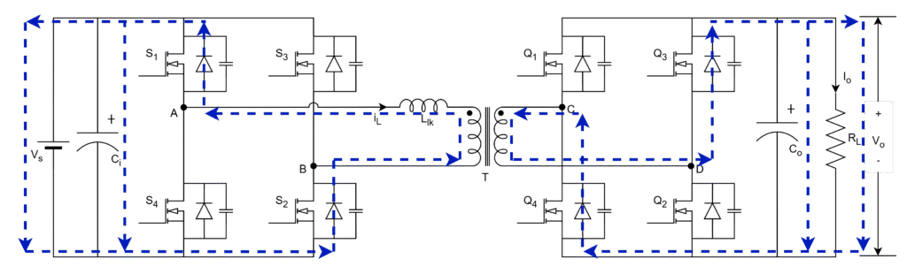
- The gate signals (S1, S2) and (Q3, Q4) are available. Hence, VAB is positive and VCD is negative.
- Since primary side VAB is positive and iL is negative, diodes (DS1, DS2) do conduct in primary side.
- Since secondary side both VCD and iL are negative, diodes (DQ3, DQ4) do conduct in secondary side.
- This stage ends when the inductor current iL reaches zero from negative.
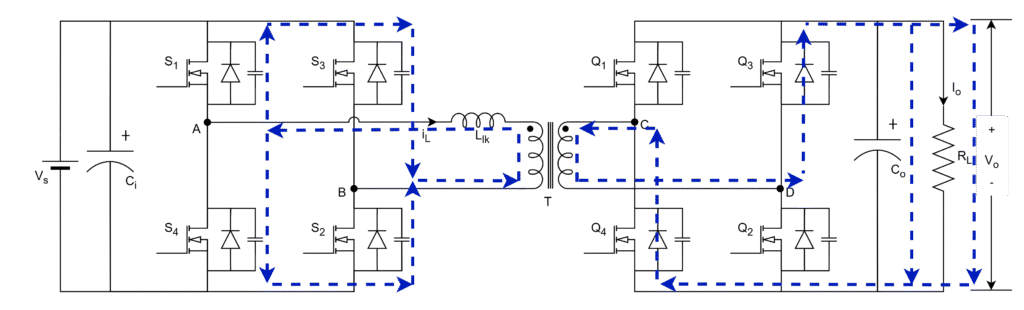
Interval-2 (t1 – t2)
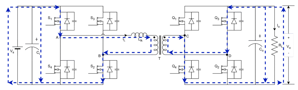
- The gate signals (S1, S2) and (Q3, Q4) are still available. Hence, VAB is positive and VCD is negative.
- Since primary side VAB and iL are positive, switches (S1, S2) do conduct in primary side.
- Since secondary side VCD is negative and iL is positive, switches (Q3, Q4) do conduct in secondary side.
- This stage ends when the inductor current reaches a positive from zero.
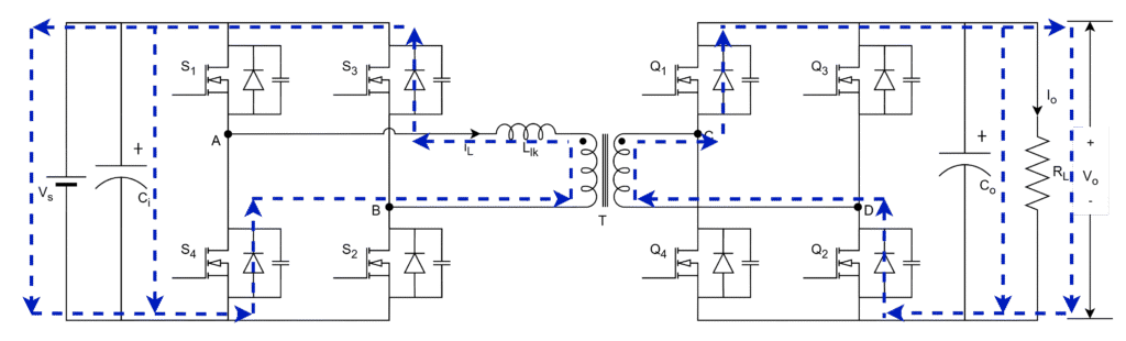
Interval-3 (t2 – t3)
- The gate signals (S1, S2) are available and all switches in secondary are in off state. Hence, iL is positive and VCD is zero. This period can be called secondary bridge dead-band region.
- Since primary side both VAB and iL are positive, only switches (S1, S2) do conduct in primary side.
- Since secondary voltage is zero and iL is positive, energy stored in inductor circulates in same direction, hence that discharges the switch capacitors (CQ1, CQ2) to 0
(i.e. Vo -> 0) and charges the switch capacitors (CQ3, CQ4) to Vo (i.e. 0 -> Vo). Therefore, secondary voltage VCD changes from -Vo -> +Vo.
- This stage ends when the inductor current charges and discharges the secondary bridge switch capacitors fully.
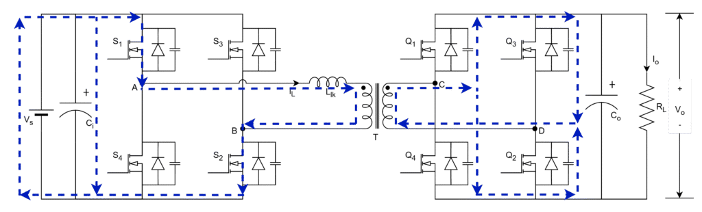
Interval-4 (t3 – t4)
- The gate signals (S1, S2) and (Q1, Q2) are available. Hence, VAB is positive and VCD is positive.
- Since primary side both VAB and iL are positive, switches (S1, S2) do conduct in primary side.
- Since secondary side both VCD and iL are positive, diodes (DQ1, DQ2) do conduct in secondary side.
- This stage ends when the primary bridge gating signals are removed.
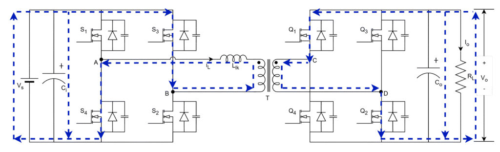
Interval-5 (t4 – t5)
- The gate signals only (Q1, Q2) are available and all switches in primary are in off state. Hence, VAB is zero and iL is positive. This period can be called primary bridge dead-band region.
- Since primary voltage is zero and iL is positive, energy stored inductor circulates in same direction, hence that discharges the switch capacitors (CS3, CS4) to 0 (i.e. Vs -> 0) and charges the capacitors (CS1, CS2) to Vs (i.e. 0 -> Vs). Therefore, primary voltage VAB changes from +Vs -> -Vs.
- Since secondary side VCD is positive and iL is positive, only diodes (DQ1, DQ2) do conduct in secondary side.
- This stage ends when the inductor current charges and discharges the primary bridge switch capacitors fully.
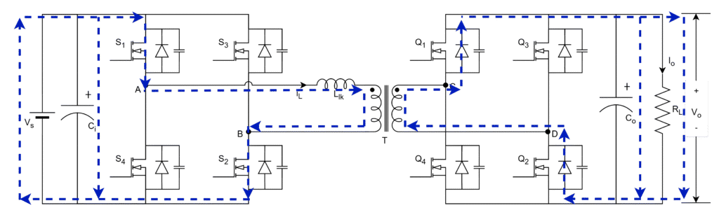
Interval-6 (t5 – t6)
- The gate signals (S3, S4) and (Q1, Q2) are available. Hence, VAB is negative and VCD is positive.
- Since primary side VAB is negative and iL is positive, diodes (DS3, DS4) do conduct in primary side.
- Since secondary side VCD and iL are positive, diodes (DQ1, DQ2) do conduct in secondary side.
- This stage ends when the inductor current reaches zero from positive.
Interval-7 (t6 – t7)
- The gate signals (S3, S4) and (Q1, Q2) are still available. Hence, VAB is negative and VCD is positive.
- Since primary side VAB and iL are negative, switches (S3, S4) do conduct in primary side.
- Since secondary side VCD is positive and iL is negative, switches (Q1, Q2) do conduct in secondary side.
- This stage ends when the inductor current reaches negative from zero.
Interval-8 (t7 – t8)
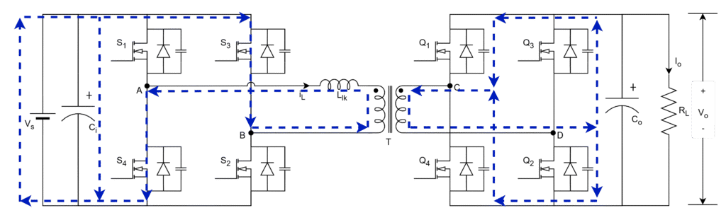
- The gate signals (S3, S4) are available and all switches in secondary are in off state. Hence, VAB is negative and VCD is zero. This period can be called secondary bridge dead-band region.
- Since primary side VAB and iL are negative, switches (S3, S4) do conduct in primary side.
- Since secondary VCD is zero and iL is negative, energy stored inductor circulates currents in same direction, hence, that discharges the switch capacitors (CQ3, CQ4) to 0 (i.e. Vo -> 0) and charges the switch capacitors (CQ1, CQ2) to Vo (i.e. 0 -> Vo). Therefore, secondary voltage VCD changes from +Vo -> -Vo.
- This stage ends when the inductor current charges and discharges the secondary bridge switch capacitors fully.
Interval-9 (t8 – t9)
- The gate signals (S3, S4) and (Q3, Q4) are available. Hence, VAB is negative and VCD is negative.
- Since primary side both VAB and iL are negative, switches (S3, S4) do conduct in primary side.
- Since secondary side VCD and iL are negative, diodes (DQ3, DQ4) do conduct in secondary side.
- This stage ends when the primary bridge gating signals are removed.
Interval-10 (t9 – Ts)
- The gate signals (Q3, Q4) are available and all switches in primary are in off state. Hence, VAB is zero and VCD is negative. This period can be called primary bridge dead-band region.
- Since primary voltage VAB is zero and iL is negative, energy stored inductor circulates current in same direction, hence that discharges the capacitors (CS1, CS2) to 0 (i.e. Vs -> 0) and charges the capacitors (CS3, CS4) to Vs (i.e. 0 -> Vs). Therefore, primary voltage VAB changes from -Vs -> +Vs.
- Since secondary side VCD and iL are negative, diodes (DQ3, DQ4) do conduct in secondary side.
- This stage ends when the inductor current charges and discharges the primary bridge switch capacitors fully.
Leave a Reply