Buck means ‘Reducing’.
Here we are reducing the voltage from input side to output side. Since voltage is reducing at output, current increases relatively compared to input current.
Input voltage (Vdc) > Output voltage (Vo), and
Input current (Idc) < Output current (Io)
Definition: The converter which reduces the input DC voltage is called buck converter or step-down converter
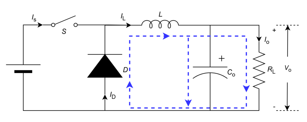
1. Buck Converter Circuit
The arrangement of power electronic semiconductor components such as switch ![]() , diode
, diode ![]() , inductor
, inductor ![]() , and capacitor
, and capacitor ![]() for buck operation is shown below figure.
for buck operation is shown below figure.
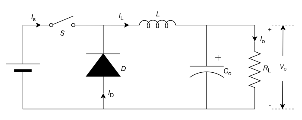
Basic Possible KVL and KCL for voltages and currents respectively from above circuit are as follows
To produce the required step-down output voltage from input voltage, pulse-width modulation (PWM) control technique is being used.
2. Buck Converter Operation
To step-down the DC input voltage, the element which can be controlled is switch (S) by it is turning ON and OFF through gate pulse. Hence, the operation of converter is divided into 2 modes.
Switch (S) ON Mode:
When switch is closed, it gives path to flow the current from one side to another side through inductor. Hence, supply positive terminal connects at diode (D) cathode and negative terminal connects at diode anode.
Therefore, VAK < 0 => Diode (D) is reverse biased and does not conduct. Acts like open circuit. Then the current path in this mode is shown below figure.
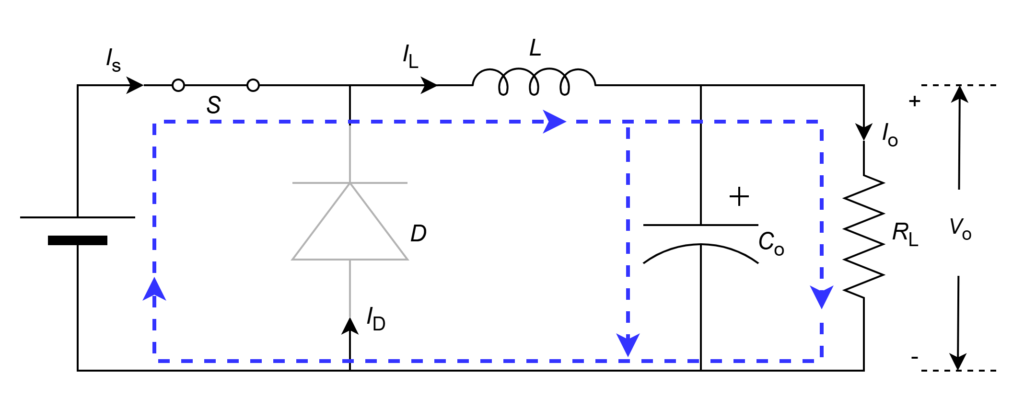
From above circuit,

The inductor current starts raising from zero due to positive inductor voltage (![]() when switch is closed (initially), the voltage drop across load starts build in similar passion. Inductor current raises linearly till the desired voltage drop built at load and then switch will open (this mode ends at this point).
when switch is closed (initially), the voltage drop across load starts build in similar passion. Inductor current raises linearly till the desired voltage drop built at load and then switch will open (this mode ends at this point).
Voltage across inductor from circuit,
![]()
Current through inductor,

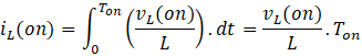
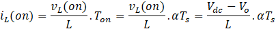
Switch turn-on period is part of one switching cycle ![]() i.e.
i.e. ![]() . Hence,
. Hence,
Switch (S) OFF Mode:
When switch is open, it does not give path to flow the current from one side to another side. Hence, inductor negative terminal connects at diode (D) cathode.
Therefore, VAK > 0 => Diode (D) is forward biased and does conduct. Acts like short circuit. Then the current path in this mode is shown below figure.
From above circuit,

When the voltage drop across load reaches its maximum desired value, switch will open. Then, current through inductor starts discharge/fall due to negative inductor voltage (![]() . Due to falling in current, the voltage drop across load starts fall. Switch will close again at minimum desired voltage drop across load (end of this mode).
. Due to falling in current, the voltage drop across load starts fall. Switch will close again at minimum desired voltage drop across load (end of this mode).
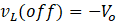
Voltage across inductor from circuit,
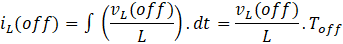
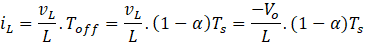
Current through inductor,

Switch turn-off period is part of one switching cycle i.e. . Hence,
Switch ON-OFF repeats the buck converter circuit operation.
In simple words,
| Switch ON | Switch OFF |
| Switch conducts | Diode conducts |
| Inductor charges | Inductor discharges |
| Capacitor charges | Capacitor discharges |
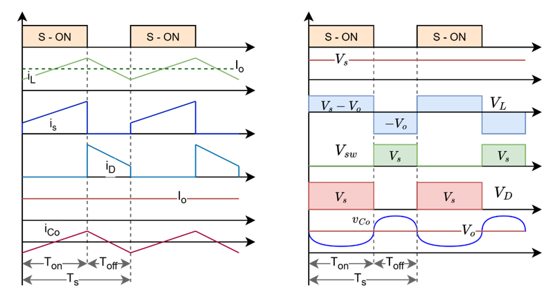
The graphical representation of voltage across and current through circuit elements are shown below
Leave a Reply