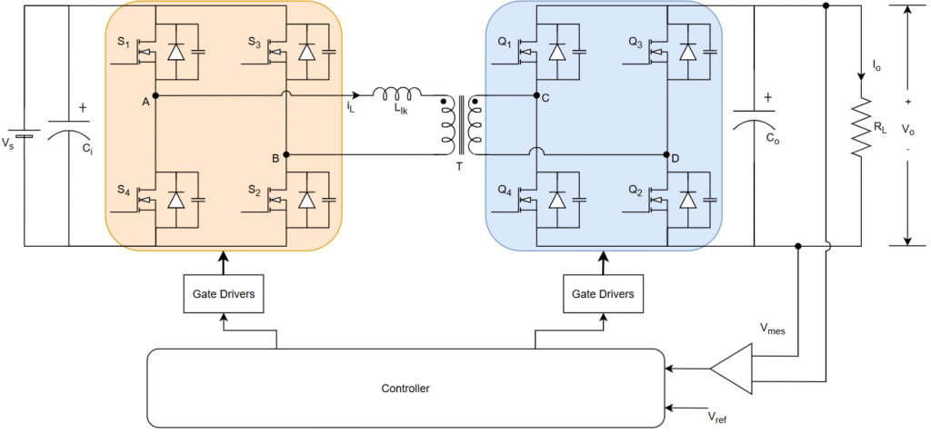
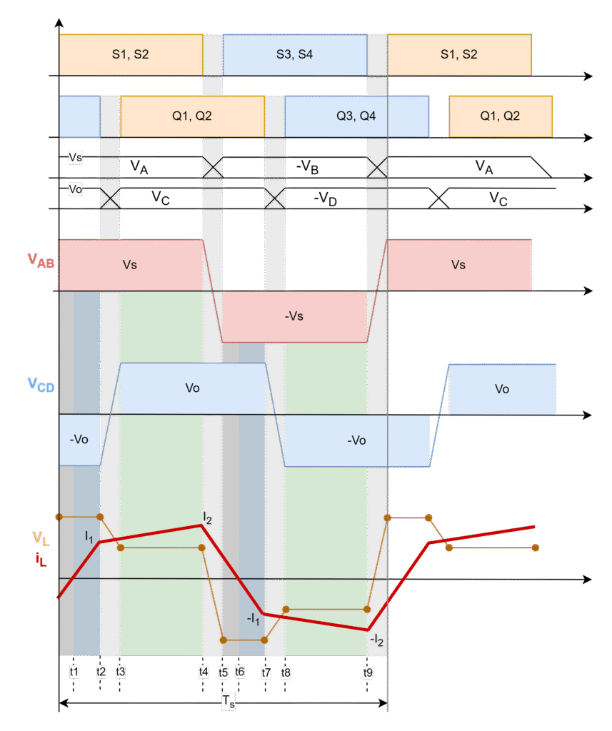
In a single-phase, dual-active bridge shown in Fig., primary and secondary bridges are controlled simultaneously. All switches operate at 50% duty ratio. The diagonal switches turn-on and turn-off together so that the output of each bridge is a square wave. The switching sequence of the converter is elaborated in detail in this section. The typical operating signals and waveforms of proposed fixed switching frequency single phase-shift control technique are given in below Fig.
The main aim of operating this converter is to regulate the output voltage for load variation at constant power. It can be done by phase-shifting (ϕ) the secondary bridge voltage (VCD) with respect to primary bridge voltage (VAB). The phase-shift angle is obtained by shifting the secondary bridge switches (Q1, Q2) and (Q3, Q4) with respect to primary bridge switches (S1, S2) and (S3, S4) respectively. Then the power flow takes place from primary bridge to secondary bridge. This power flow direction can be easily changed by reversing the phase shift between the two bridges. Hence, it is possible to obtain bidirectional power transfer with ease in a dual-active bridge converter.
The switching sequence of DAB converter is divided into 10 intervals based on the
- Inductor current waveform
- Phase-shift between the primary and secondary bridge
- Dead-time between the leg switches.
The operation modes are explained in following post.
Leave a Reply