Flyback means ‘returning’
Flyback converter generally uses for step-down or step-up with isolation for low power applications. Most commonly uses in auxiliary power supplies.
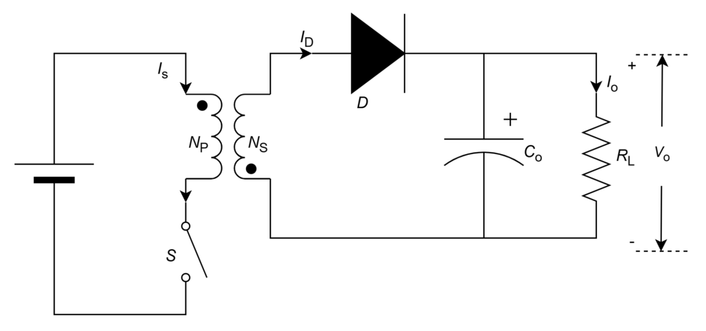
The arrangement of power electronic semiconductor components such as switch (, diode
, coupled inductor
, and capacitor
for flyback converter operation is shown below figure.
By applying KVL and KCL
From primary circuit,


From secondary circuit,


From Transformer,


Flyback Converter Operation
To change the DC input voltage to required DC output voltage , the element which can be controlled is switch (S) by turning ON and OFF through gate pulse. Hence, the operation of converter is divided into 2 modes.
Switch (S) ON mode
When switch is closed, it gives path to flow the input current in primary side. The input/switch current is combination of magnetizing current and primary current.
Since switch is closed, the entire power supply voltage () appears across primary winding/magnetizing inductance. Therefore, secondary winding voltage is negative (
) due to transformer dot polarity. Then, negative voltage terminal connects at diode (D) anode.
Therefore, => Diode (D) is reverse biased and does not conduct. Acts like open circuit. That means secondary/diode current is zero.
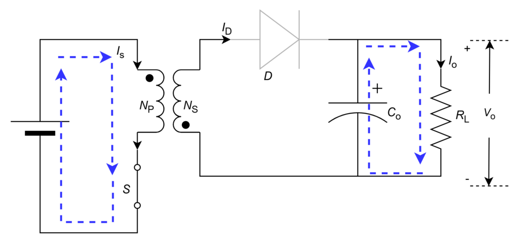
Since secondary winding is open and current is zero, input supply current cannot flow through primary winding also due to power balance of transformer windings. That means, entire input current flows through magnetizing inductance winding (![]() ) and same through switch. This current ramps up slowly for entire duration of ON-period from zero when switch is closed (initially) and stores energy. The current path in this mode is shown in figure.
) and same through switch. This current ramps up slowly for entire duration of ON-period from zero when switch is closed (initially) and stores energy. The current path in this mode is shown in figure.
From primary circuit,


From secondary circuit,


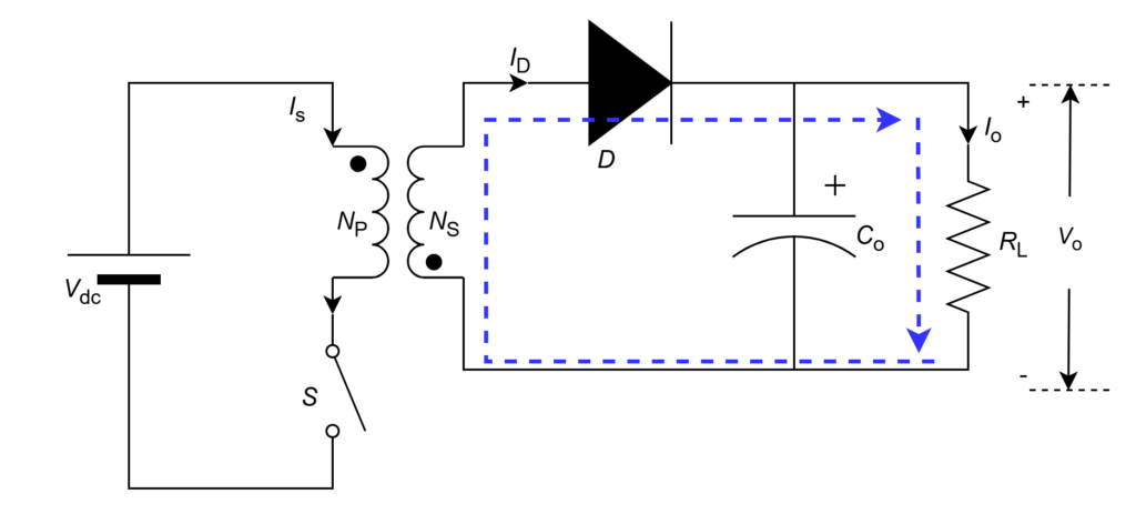
Switch (S) OFF mode
When switch is open, it cannot give path to flow the input current in primary side. Since switch is open, the energy stored in the magnetizing winding starts to discharge and flows through primary winding in same direction. Hence, negative voltage develops across primary. Therefore, secondary winding developing voltage is positive due to transformer dot polarity. Then, positive voltage terminal connects at diode (D) anode.
Therefore, => Diode (D) is forward biased and does conduct. Acts like short circuit.
The energy stored in the magnetizing winding starts to discharge and flows through primary winding in same direction. This current ramps down slowly for entire duration of OFF-period from peak when switch is open. Hence, secondary winding current flows due to power balance of transformer windings. The current path in this mode is shown below figure.
From secondary circuit,


From primary circuit,


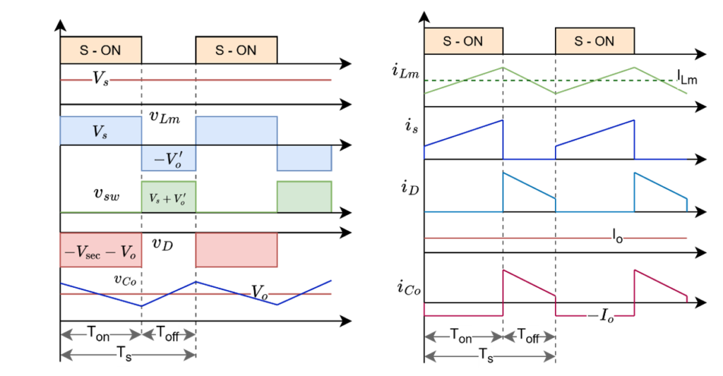
The waveforms of flyback converter in entire full cycle operation are as follows
Leave a Reply