In this control, the duty cycle varies by phase-shifting the PWM pulses respect to each-other with fixed frequency and turn-on time of each pulse.
duty = Function (phase-shift)
Full-bridge Inverter:
In general, normal full-bridge inverter shown below which is also called as 2-leg converter consist of 4 switches.
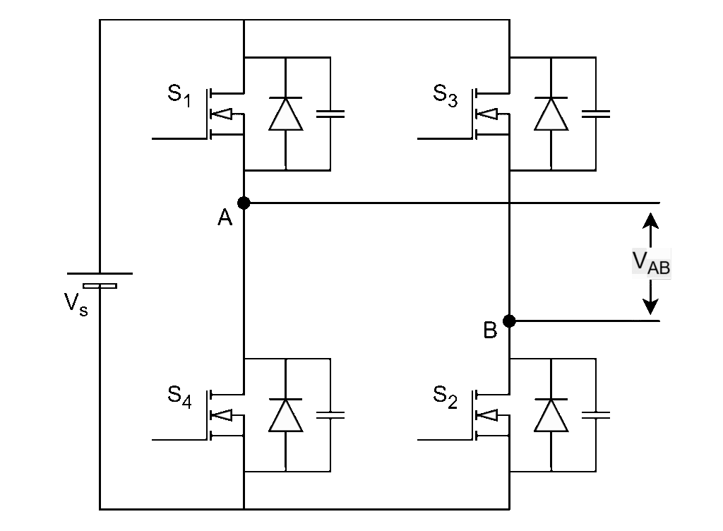
Leg-1 switches : S1, S4
Leg-2 switches : S3, S2
Diagonal switch pairs : (S1, S2) & (S3, S4)
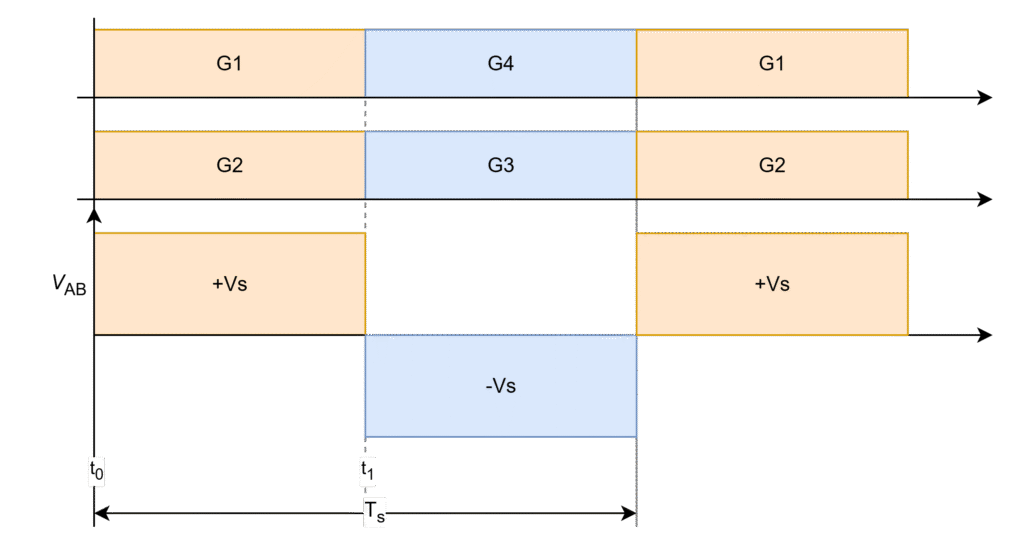
- Each leg should operate with complimentary (i.e. 180o phase) pulses with 50% duty cycle.
- Each diagonal switch pair shall operate simultaneously.
G1 – G4 are gating signals of switches S1 – S4 respectively.
The Inverter output voltage generates with positive input voltage when S1 and S2 are conducting (t0 – t1) and with negative input voltage when S3 and S4 are conducting (t1 – Ts) in one full-switching cycle (0 – Ts) as shown in below figure and it repeats. This is a normal inverter operation.
Phase-shift Control:
The phase-shift control is implemented by delaying the phase in-between diagonal switch pairs i.e. between S1 and S2; and between S3 and S4.
The leg-1 switches (S1, S4) are at original positions, leg-2 switches (S2, S3) shift the starting point some angle respectively as shown in below figure.
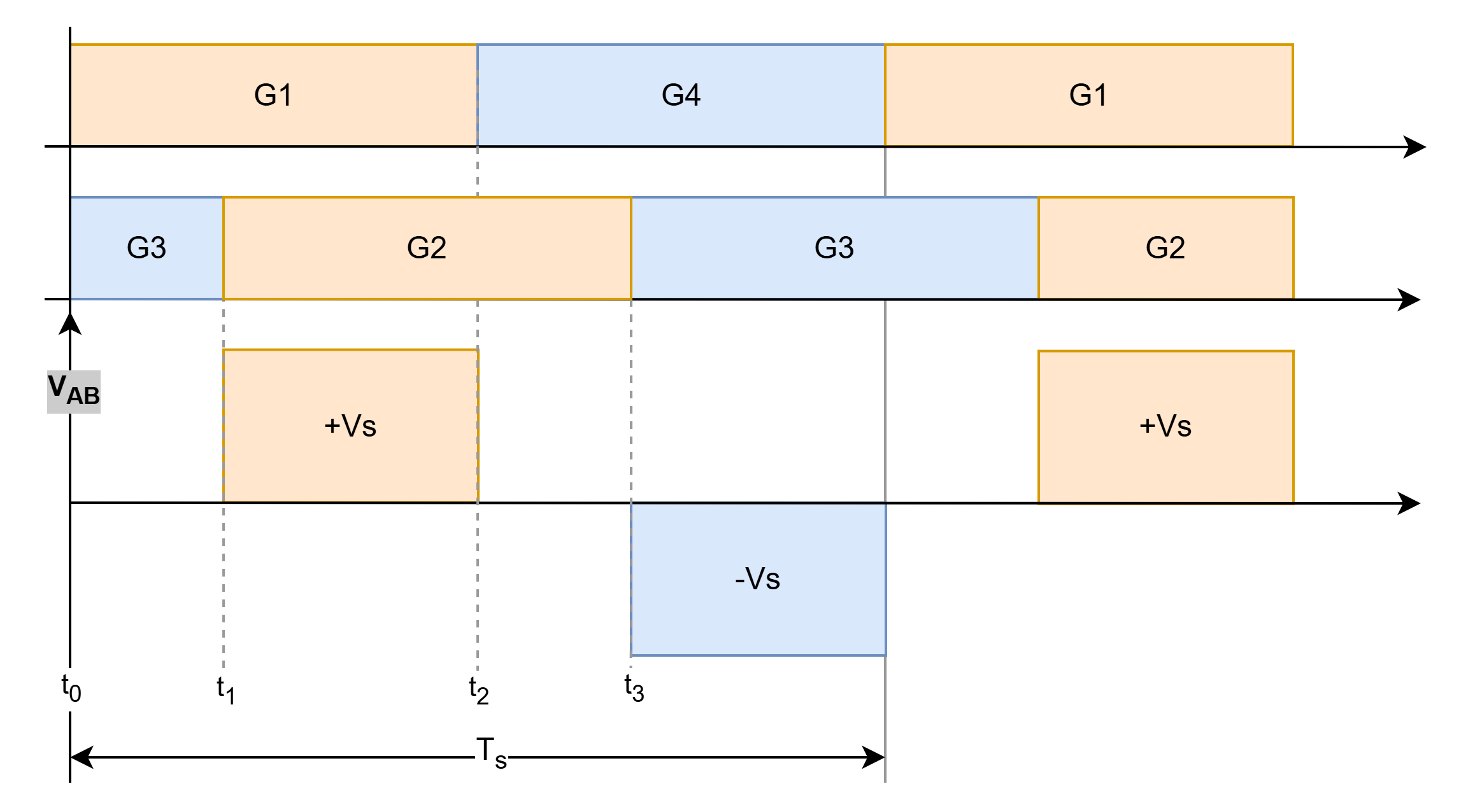
- When S1 and S2 are conducting @ (t1 – t2), positive input voltage (+Vs)
- When S3 and S4 are conducting @ (t3 – Ts), negative input voltage (-Vs)
- When both high-side switches (S1, S3) @ (t0 – t1) or both low-side switches (S2, S4) @ (t2 – t3) are conducting, ZERO voltage
Due to this phase-shift, the time period (pulse width or duty) of generating inverter output voltage will be reduced with introducing the zero-voltage stages.
Hence, the output voltage can be controlled using phase-shift control method in this manner.
Leave a Reply