Circuit Description
The circuit diagram is shown below. It is a combination of full-bridge inverter (DC-AC), high-frequency transformer, and full-wave rectifier (AC-DC) with diodes
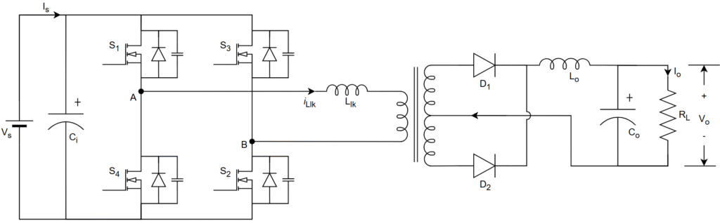
DC input is given to full-bridge inverter which converts the DC to high frequency (HF) AC –>
HF AC is goes to HF transformer and it stepup/stepdown as per design requirement –>
The transformer secondary HF AC goes to full-wave rectifier which converts AC to regulated DC –>
This regulated DC goes through LC filter which filters the AC signals and produce pure DC.
Leave a Reply