Power factor correction (PFC) means improving
It is defined as how much active power is drawn from grid in the amount of total power.
In simple terms,
Total Power (S) = Active power (P) + Reactive power (Q)
Total power (S) –> Apparent power = VrmsIrms
Active (Real) power (P) –> Useful power = VrmsIrms*cos(Φ)
Reactive power (Q) –> Useless = VrmsIrms*sin(Φ)
Here,
Power factor = P/S = cos(Φ)
It is defined as ratio of active power to total power
Power factor is high –> Useful / Active / Real power is high
Power factor is low –> Reactive / Useless power is high
Where,
Φ is the phase angle between the voltage and current (deg.)
- Maximum value –> 1 @ Φ = 0
- Minimum value –> 0 @ Φ = 90o
Examples:
- Resistive Circuit
Connected load to the grid is pure resistive nature, See below Fig.
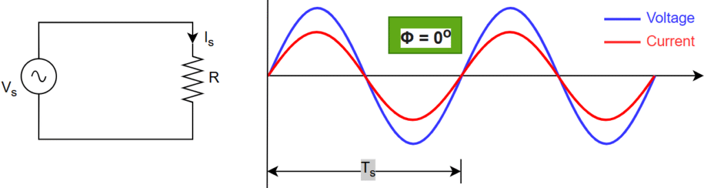
The current drawn is in-phase with the voltage –> Φ = 0 –> pf = 1 –> S = P
Total power (S) = Active power (P)
- Inductive Circuit
Connected load to the grid is pure inductive nature, See below Fig.
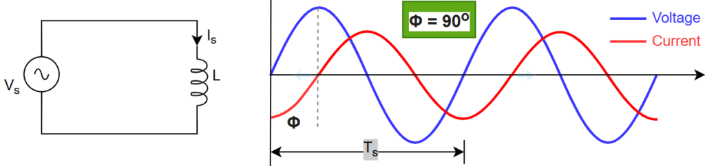
The drawing current is lags with the voltage –> Φ = 90o –> pf = 0 –> S = Q
The average of active power is “ZERO”
Total power (S) = Reactive power (Q)
- Capacitive Circuit
Connected load to the grid is pure capacitive nature, See below Fig.
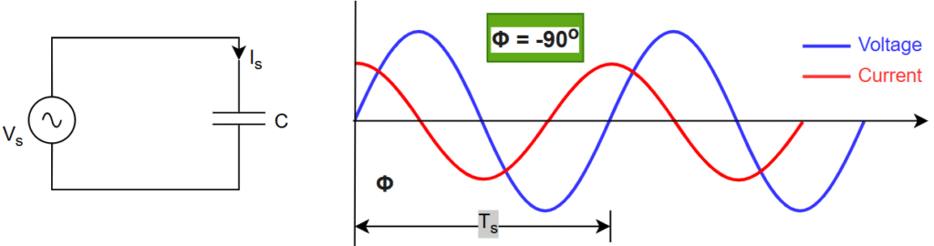
The drawing current is leads with the voltage –> Φ = -90o –> pf = 0 –> S = Q
The average of active power is “ZERO”
Total power (S) = Reactive power (Q)
Conclusions:
- Power factor : P/S
- Power factor value range : 0 to 1
- Power factor is directly proportional to active power
- Pure inductive / capacitive circuit power factor is ‘0’, and its average active power is ZERO
Leave a Reply