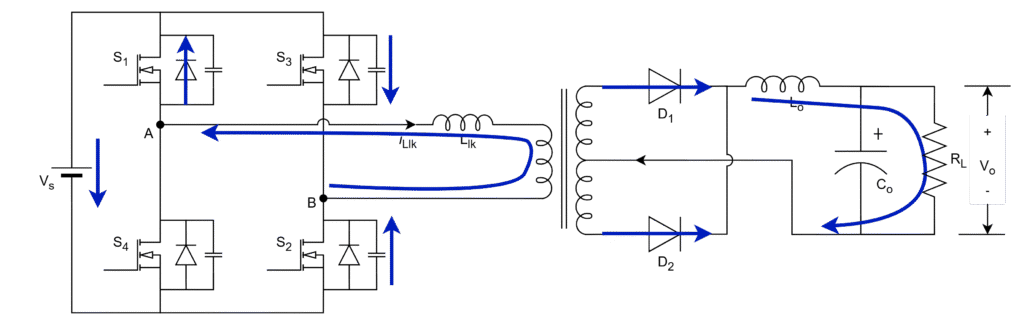
The PSFB circuit with the phase-shift PWM control method can be divided into 10 operating modes. The typical operating signals and waveforms are given below.
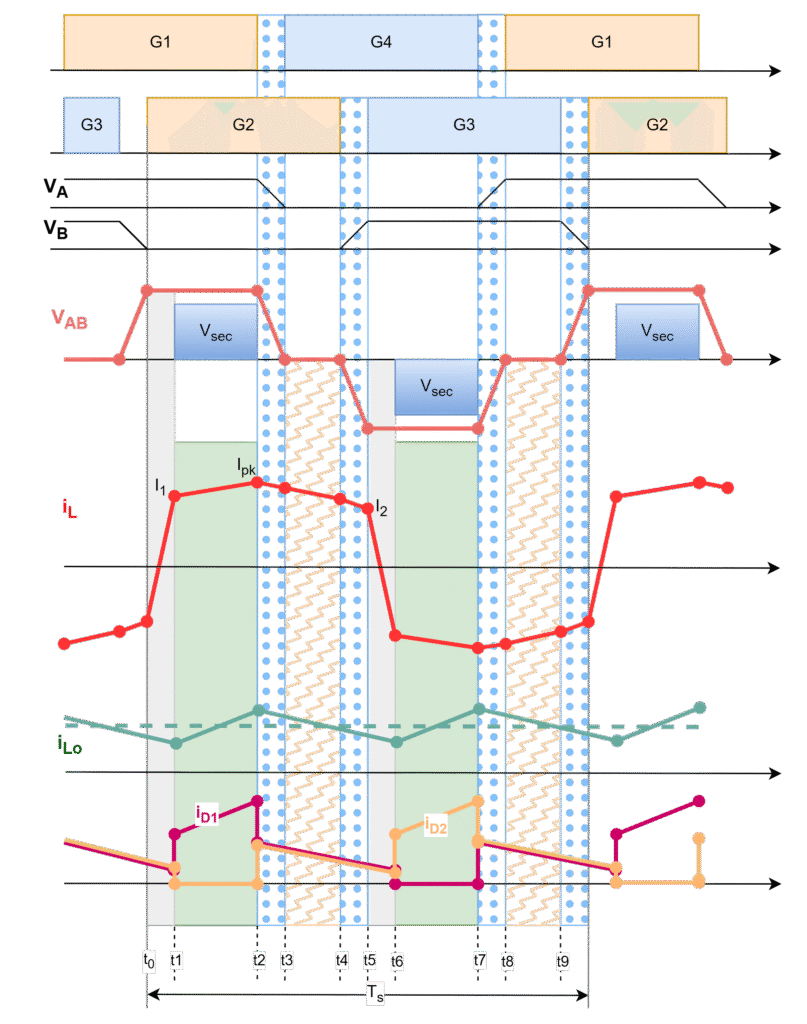
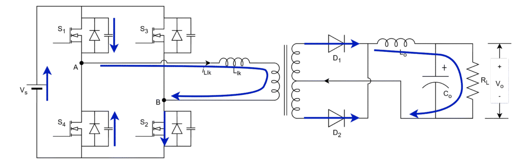
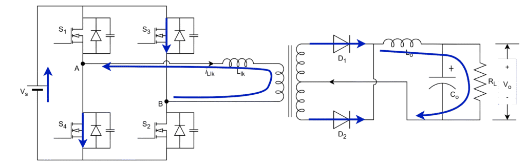
Mode-1 (t0 -t1): Duty cycle loss mode
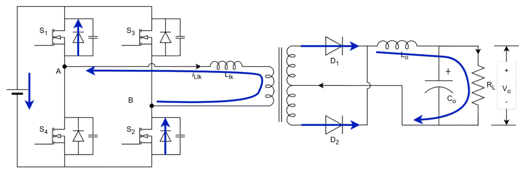
- G1 and G2 gating signals are existed –> Positive inverter output voltage, VAB = + Vs
- Negative inductor current period –> Body diodes should conduct –> DS1, DS2
- Positive inductor current period –> Active switches should conduct –> S1, S2
- Inductor current lags behind the voltage and it stores the energy and reaches refelected output current (ILo_min) with the slope of
- The output inductor still is in discharge mode through both the diodes D1 and D2, hence secondry side voltage is zero (short circuited) and then primary side voltage is zero.
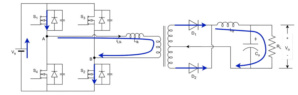
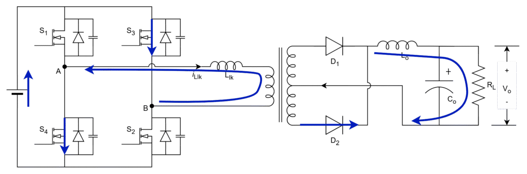
Mode-2 (t1 – t2): Power Delivery Mode
- G1 and G2 gating signals are existed –> Positive inverter output voltage, VAB = + Vs
- Positive inductor current –> Active switches should conduct –> S1, S2
- Inductor charges with change in slope due to filter inductor adds up to the primary leakage inductor
- Output inductor starts charging through diode D1 and power transfer to the load
Mode-3 (t2 – t3): Dead Zone Mode
- Only G2 gating signals is existed –> No inverter output voltage, VAB = 0
- Positive inductor current –> Switch should conduct –> S2
- The switch S1 capacitor starts charging and at the same time, switch S4 capacitor starts discharging
- Slope of resonant inductor current is same as output inductor current as it is discharging through D1 and D2
- Dead time should be enough to completely charge and discharge the switch capacitors
After capacitors fully charge and discharge, the discharged capacitor switch provides the freewheeling path for the inductor current through body diode DS4 (as shown in next mode). This ensure that switch turns-on with a zero-voltage.
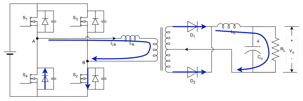
Mode-4 (t3 – t4): Freewheeling Mode
- G2 and G4 gating signals are existed –> No inverter output voltage, VAB = 0
- Positive inductor current –> Switch S2 and body diode of S4 should conduct –> S2, DS4
- Body diode of S4 provides the freewheeling path for the resonant inductor current with reduced slope since output indcutor comes into series
- In freewheeling operation, energy will not transfer to secondary since the output indcutor is in discharge throgh both diodes and hence secondary voltage is zero.
Mode-5 (t4 – t5): Dead Zone Mode
- Only G4 gating signal is existed –> No inverter output voltage, VAB = 0
- Positive inductor current –> Body diode should conduct –> DS4
- The turned-off switch S2 capacitor starts charging and at the same time, switch S3 capacitor starts discharging
- Slope of resonant inductor current is same as output inductor current as it is discharging through D1 and D2
- Dead time should be enough to completely charge and discharge the switch capacitors
After capacitors fully charge and discharge, the discharged capacitor switch provides the freewheeling path for the inductor current through body diode DS3 (as shown in next mode). This ensure that switch turns-on with a zero-voltage
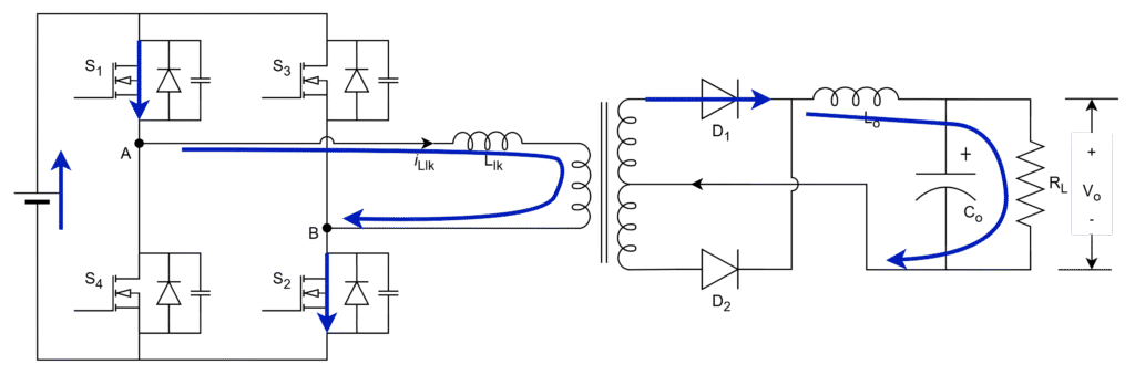
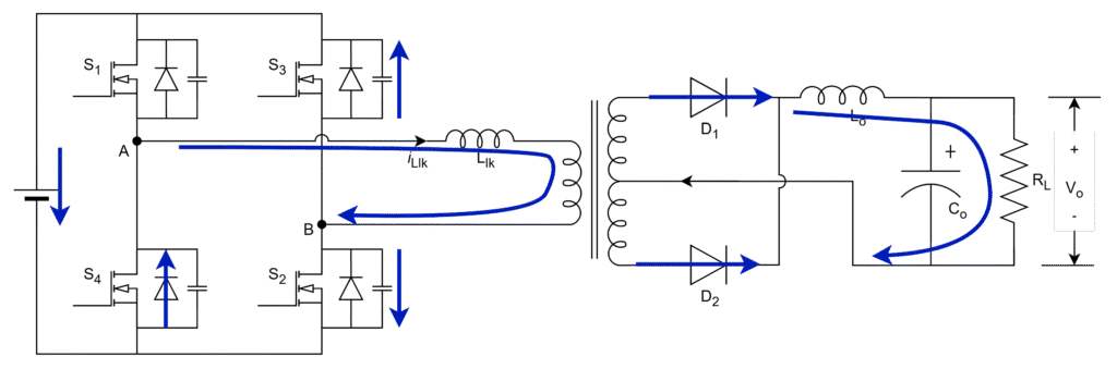
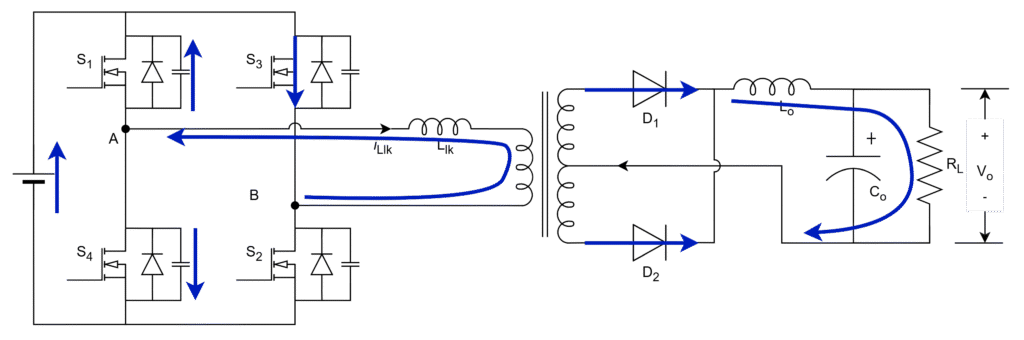
Mode-6 (t5 – t6): Duty Cycle loss Mode
- G4 and G3 gating signal is existed –> Inverter output voltage, VAB = – Vs
- Positive inductor current –> Body diode should conduct –> DS4 , DS3
- Negative inductor current –> Active switches should conduct –> S4 , S3
- Inductor current lags behind the voltage and it release the energy rapidly with the slope of
- The output inductor still is in discharge mode through both the diodes D1 and D2, hence secondry side voltage is zero (short circuited) and then primary side voltage is zero.
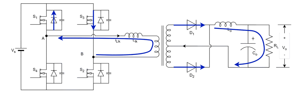
Mode-7 (t6 – t7): Power Transfer Mode
- G3 and G4 gating signals are existed –> Negative inverter output voltage, VAB = – Vs
- negative inductor current –> Switches should conduct –> S3, S4
- Inductor charges with change in slope due to filter inductor adds up to the primary leakage inductor
- Output inductor starts charging through diode D2 and power transfer to the load
Mode-8 (t7 – t8): Dead Zone Mode
- Only G3 gating signal is existed –> No inverter output voltage, VAB = 0
- Negative inductor current –> Switch should conduct –> S3
- The turned-off switch S4 capacitor starts charge and at the same time, switch S1 capacitor starts discharging
- Slope of resonant inductor current is same as output inductor current as it is discharging through D1 and D2
- Dead time should be enough to completely charge and discharge the switch capacitors
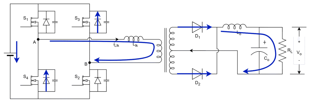
Mode-9 (t8 – t9): Freewheeling Mode
- G1 and G3 gating signal is existed –> No inverter output voltage, VAB = 0
- Negative inductor current –> Switch S3 and body diode of S1 should conduct –> S3 , DS1
- Body diode of S1 provides the freewheeling path for the resonant inductor current with reduced slope since output indcutor comes into series
- In freewheeling operation, energy will not transfer to secondary since the output indcutor is in discharge throgh both diodes and hence secondary voltage is zero.
Mode-10 (t9 – Ts): Dead Zone Mode
- Only G1 gating signal is existed –> No inverter output voltage, VAB = 0
- Negative inductor current –> Body diode should conduct –> DS1
- The turned-off switch S3 capacitor starts charge and at the same time, switch S2 capacitor starts discharging
- Slope of resonant inductor current is same as output inductor current as it is discharging through D1 and D2
- Dead time should be enough to completely charge and discharge the switch capacitors
The summarization of these operation modes of PSFB resonant converter is given in operation summary
Leave a Reply