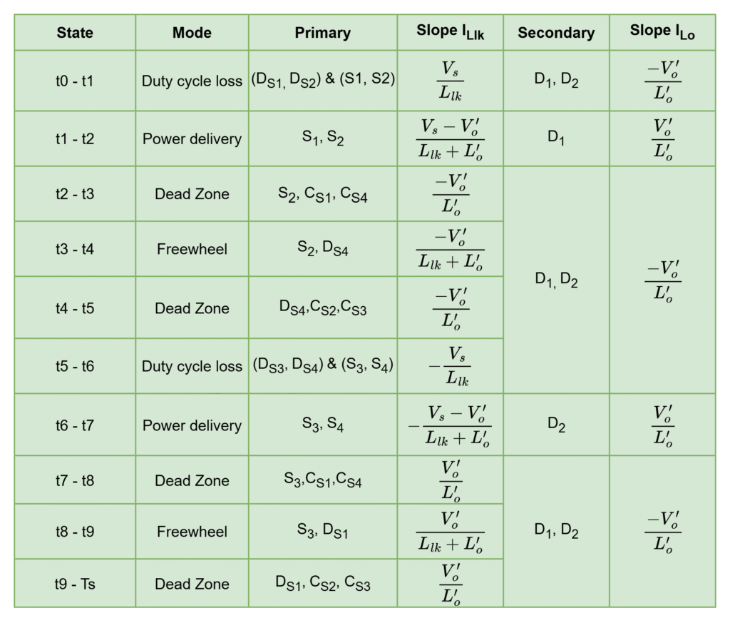
The PSFB resonant converter full-cycle operation divided into 10 operating modes: (t0 – Ts). All modes in this cycle are divided into mainly 4 modes
- Power Transfer Mode
- Dead Zone Mode
- Freewheeling Mode
- Duty Cycle loss Mode
At any period of time in the operation belongs to above any one of mode.
Power Transfer Mode
In this mode, only diagonal active switch pair conduct (S1, S2) or (S3, S4) and energy transfers to secondary side (strictly not body diodes)
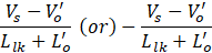
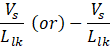
The resonant inductor current changes in this mode and reaches peak with the slope of
The output inductor charges through diode D1 or diode D2 with the slope of

Power Transfer Mode = function (Diagonal switches) = function (Resonant inductor)
Dead Zone Mode
In this mode, only one switch is active. No energy transfer to secondary side. The turning-off and turning-on switch output capacitors charge (0 -> Vs) and discharges (Vs -> 0) respectively.
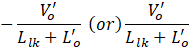
The resonant inductor current changes from peak with slope of output inductor current

The output inductor discharges through both output diodes D1 and D2 with the slope of

Dead zone period = function (Switch capacitances, resonant inductor)
Freewheeling Mode
In this mode, either low side or high side switches conduct together and no energy transfer to secondary: (S1 & DS3) or (S2 & DS4) or (S3, DS1) or (S4, DS2). In this, only one active switch and only one-body diode conduct. Hence, inverter output voltage is ZERO.
The resonant inductor current changes with slope of
The output inductor discharges through both output diodes D1 and D2 with the slope of

Freewheeling period = function (both high-side or both low-side devices) = function (Resonant inductor)
Duty cycle loss Mode
In this mode, diagonal switches or body diodes conduct based on the resonant inductor current direction. Hence, inverter output voltage exists. Even after existing the primary side voltage, secondary side transformer still short circuited due to discharge of output inductor current i.e. no secondary voltage existed.
- This mode occurs during the resonant inductor current rising or falling edges
- The rising edge or falling edge times depends on the resonant inductor value
The resonant inductor current changes with slope of
The output inductor discharges through both output diodes D1 and D2 with the slope of
Duty cycle loss mode = function (inductor current rising/falling edge) = function (Llk)
Leave a Reply