Variable frequency control, as name saying, this type of control keep on change the frequency for controlling the converter output voltage.
Vo = Function (frequency)
In this control, the PWM pulse frequency either increases or decreases to get the required output voltage after the design as per reference value given.
Full-bridge Inverter:
In general, normal full-bridge inverter shown below which is also called as 2-leg converter consist of 4 switches.
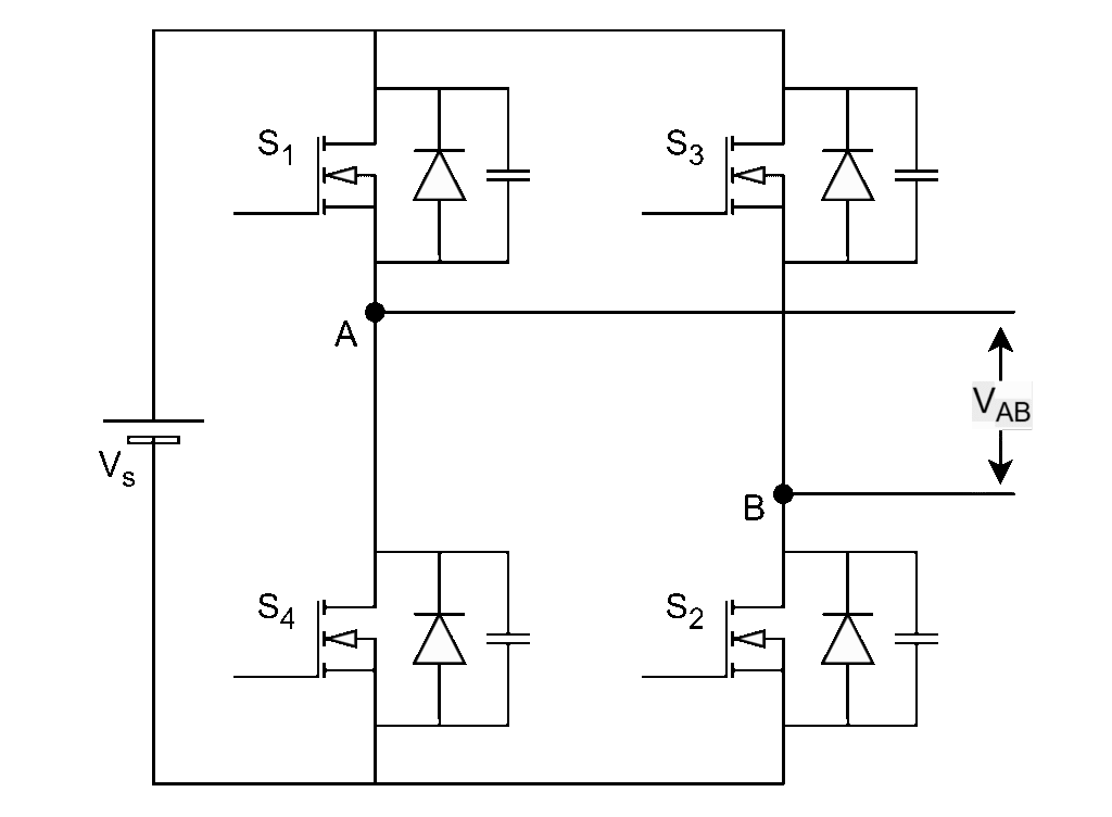
Leg-1 switches : S1, S4
Leg-2 switches : S3, S2
Diagonal switch pairs : (S1, S2) & (S3, S4)
- Each leg should operate with complimentary (i.e. 180o phase) pulses with 50% duty cycle.
- Each diagonal switch pair shall operate simultaneously.
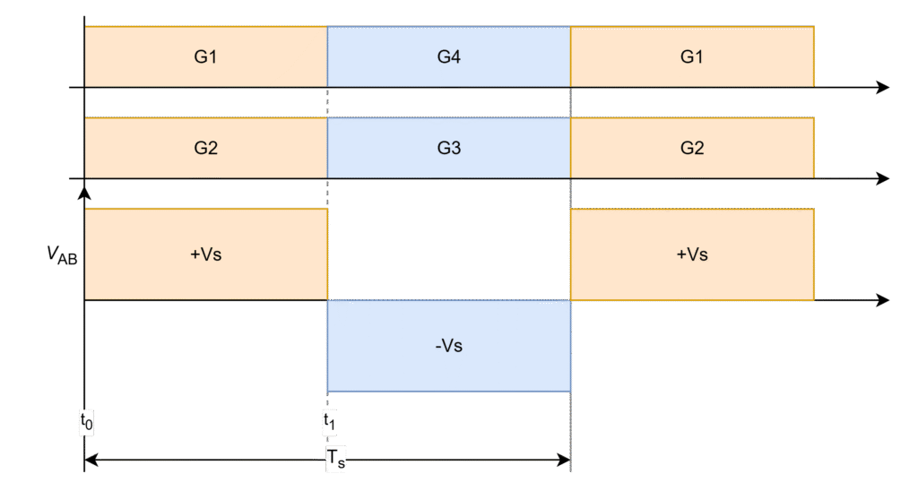
G1 – G4 are gating signals of switches S1 – S4 respectively.
The Inverter output voltage generates with positive input voltage when S1 and S2 are conducting (t0 – t1) and with negative input voltage when S3 and S4 are conducting (t1 – Ts) in one full-switching cycle (0 – Ts) as shown in below figure and it repeats. This is a normal inverter operation.
Variable Frequency Control:
The variable frequency control is implemented by increasing and decreasing the switching frequency pulse-widths of switch pairs i.e. (S1 and S2) and (S3 and S4).
In more detailed way,
- To maintain the output voltage at design point in cases of the input voltage reduction or the load power increment, the switching frequency needs to be reduced, so that switching time increases. This indicates the increase in pulse width time period increases the inverter output voltage (VAB) and then therefore increases the effective output voltage.
- To maintain the output voltage at design point in cases of the input voltage increment or the load power reduction, the switching frequency needs to be increased, so that switching time decreases. This indicates the decrease in pulse width time period decrease the inverter output voltage (VAB) and then therefore decreases the effective output voltage.
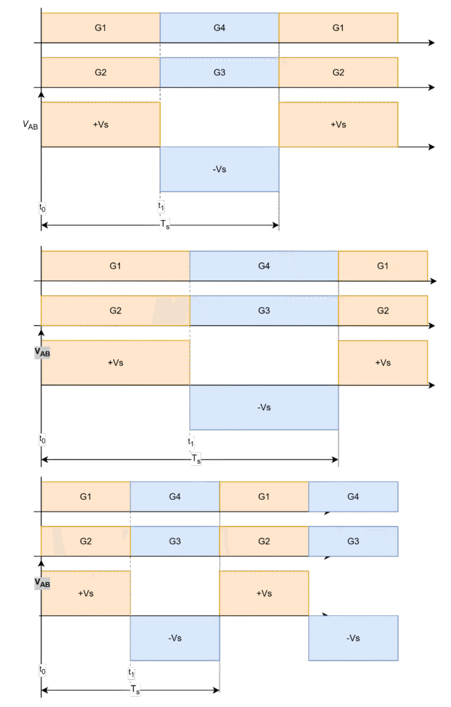
- When S1 and S2 are conducting @ (t0 – t1), positive input voltage (+Vs)
- When S3 and S4 are conducting @ (t1 – Ts), negative input voltage (-Vs)
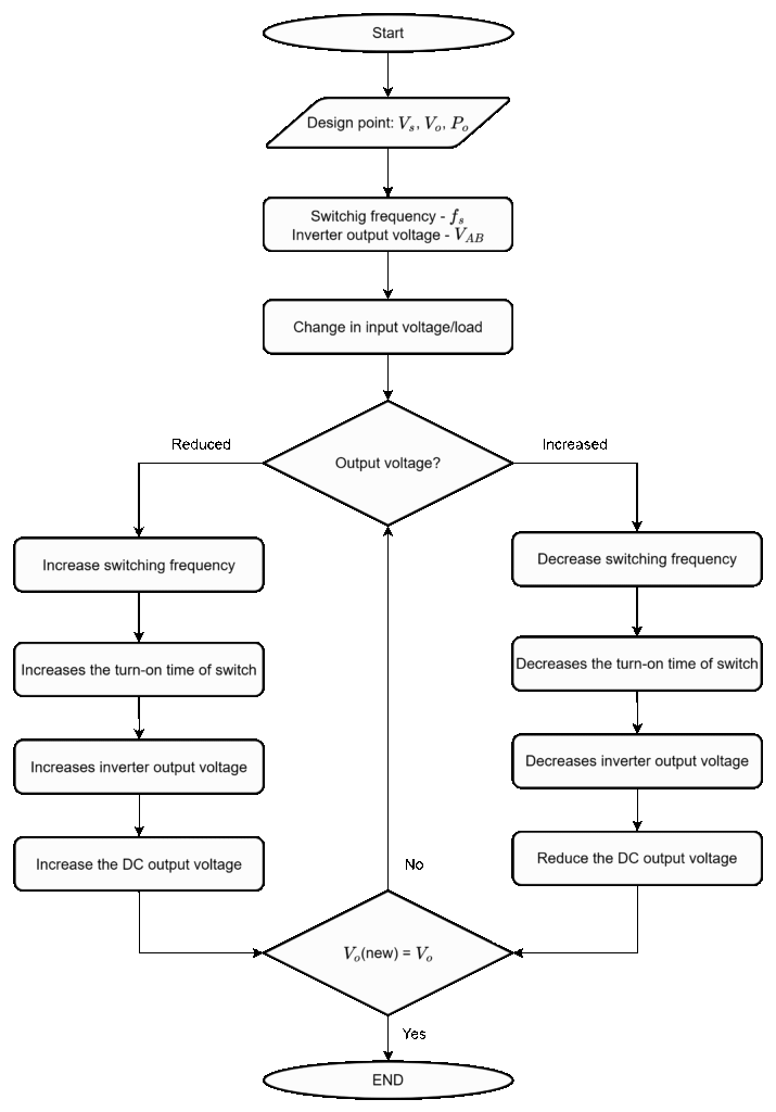
The output voltage can be controlled using varible frequency control method in this manner by controlling the inverter output voltage (VAB). The flow chart of frequency control is shown below.
Leave a Reply