The power factor correction circuit is required to improve the power factor by drawing the sinusoidal current which is in-phase with the supply voltage.
Ideally power factor 1 is good for the system. Mostly diode bridge rectifier is used for AC to DC power conversion due to uncontrolled and cost effective. But due to uncontrolled bridge rectifier, a non-sinusoidal current will be drawn from the grid.
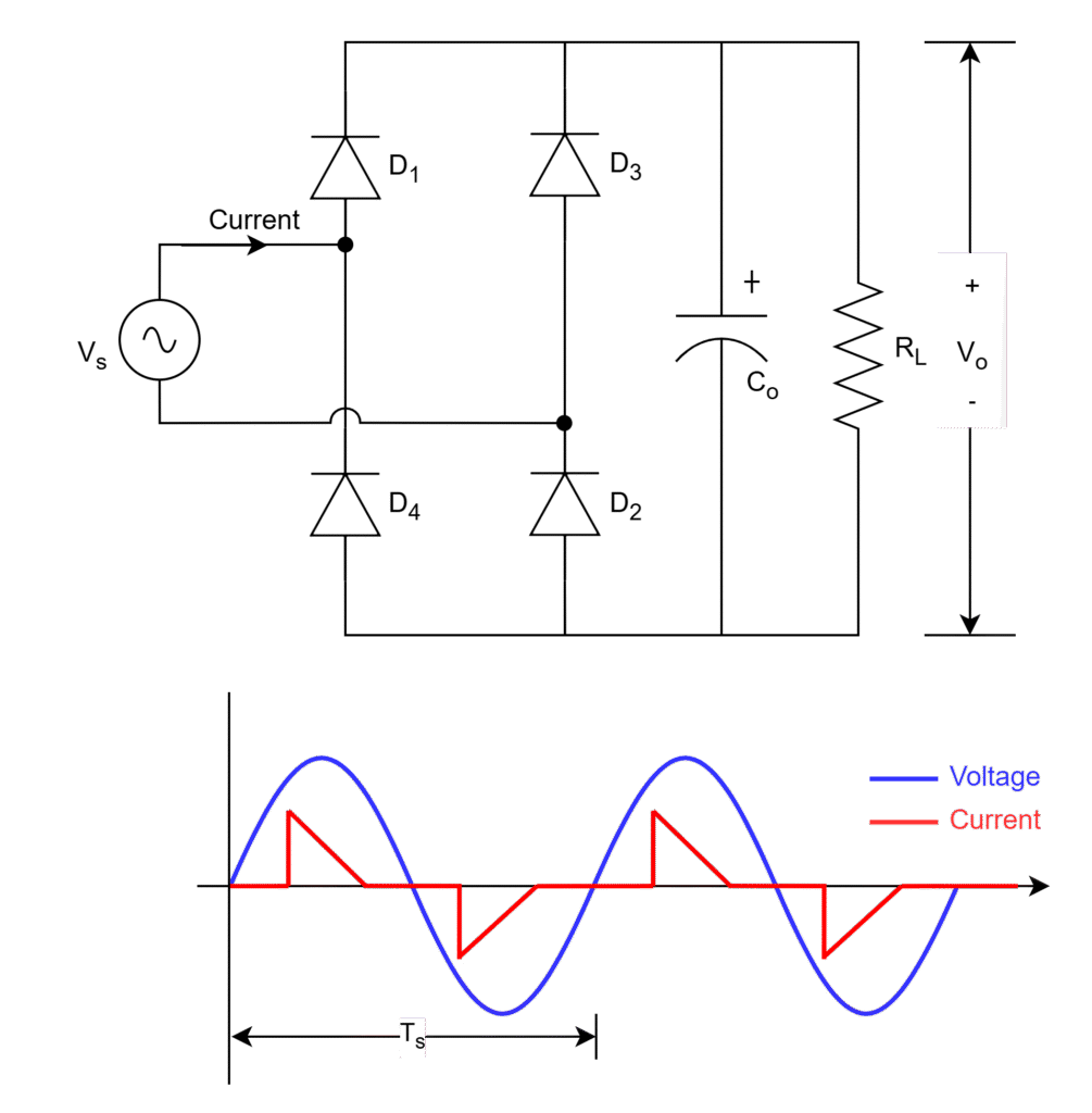
Non-sinusoidal current produce
- Harmonics
- High peak currents
- Low power factor
- High THD
It also affects the parallel loads which are connected same grid.
Passive components can be used to improve the power factor but these can be used at low power (<100 W) ranges because high power range passive components will be bulky for power factor correction.
It is also worthy to know that,
- Diode voltage drop is more than the MOSFET/IGBT. Hence, the conduction losses are more with diode bridge rectifier. Therefore, efficiency also reduces.
- No control over the diodes, DC output is not stable, changes with fluctuations in AC grid voltage which is not feasible for some applications especially stiff DC voltage is required.
The circuit shown below is an one type of power factor correction (PFC) topology which used to draw a sinusoidal supply current in-phase with the supply voltage. The controlling of switches operates such a way that both voltage and current are in-phase while drawing from grid.
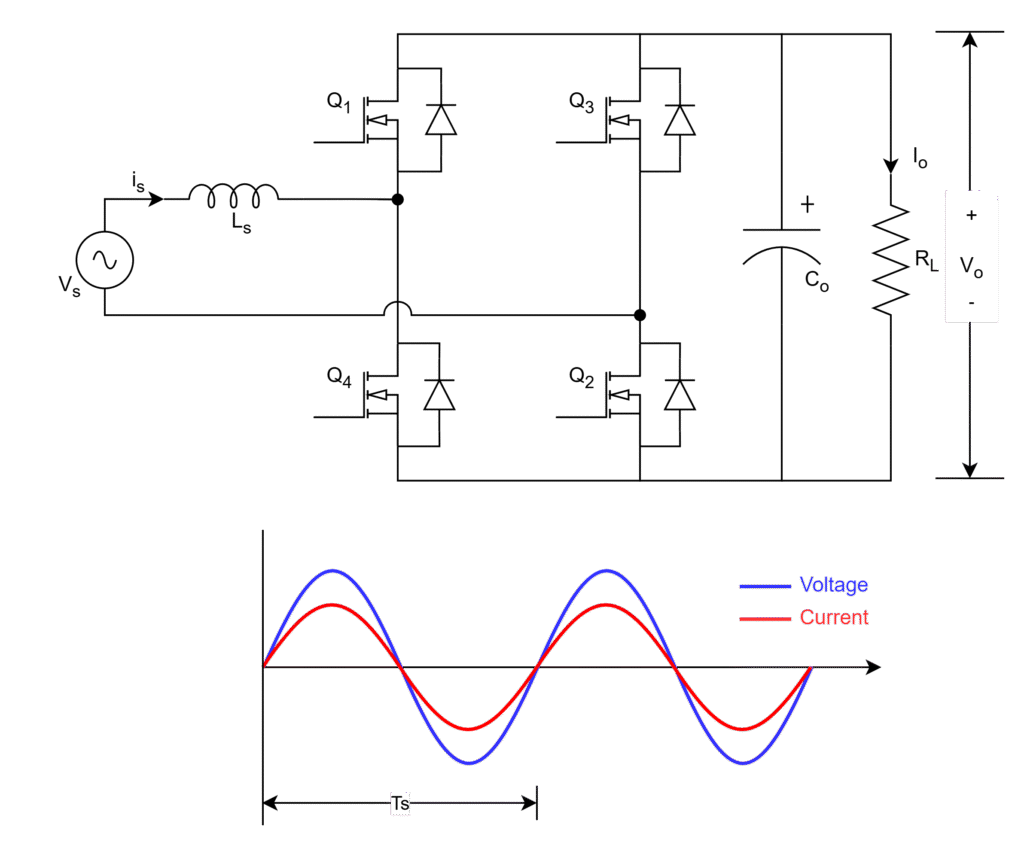
Due to in-phase sinusoidal current,
- Low Harmonics
- High power factor
- Low THD
- Low peak currents
Due to MOSFETs low voltage drop, efficiency improves and controlled stiff DC bus voltage at the load even for fluctuations in AC grid voltage.
Leave a Reply