The ZVS analysis with its considerations and derivation of critical/boundary equations to operate circuit shown in PSFB circuit and operation modes are discussed in PSFB operation with turn-on loss-free converter are discussed below.
In simple words, achieving ZVS means the MOSFET is turning-ON with zero voltage across it. This can happen when the internal output capacitor of MOSFET is fully discharged. The capacitor can be discharged by resonating it with the inductor (Llk) in resonant circuit.
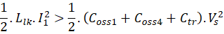
In other words, the energy stored in inductors must be more than the MOSFET output capacitive energy to discharge it with-in deadtime i.e.
The energy storage and involvement of elements in circuits are different to each leg in the full bridge. Due to this, the converter behavior is not symmetrical with both legs.
ZVS for Leg-1 (S1 & S4)
For Leg-1 (S1 & S4), the inductive energy available is low due to only resonant inductor stores energy and uses this energy to discharge the entire capacitive energy stored in the MOSFETs and transformer (Coss1+Coss2+Ctr).
Current and voltage
are in the circuit when S1 and S2 switches are taking transitions.
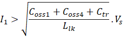
The minimum current should maintain to achieve ZVS for S1 and S2 are
Due to low inductive energy, the minimum dead-time requires to completely charge/discharge the capacitors is as follows:
The capacitor energy charge/discharge in sinusoidal manner with period of resonant time (
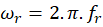
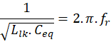
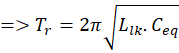
Where,
The peak voltage occurs at quarter of total period in a sinusoidal wave. Hence it is .
Therefore, the minimum dead time is required is

ZVS for Leg-2 (S2 & S3)
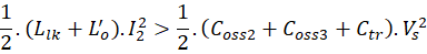
For Leg-2 (S2 & S3), the inductive energy available is high compared to another leg due to output inductor along with resonant inductor is involves in storing and uses the energy to discharge the entire capacitive energy stored in the MOSFETs and transformer (Coss2+Coss3+Ctr).
Current and voltage
are in the circuit when S1 and S2 switches are taking transitions.
The minimum current should maintain to achieve ZVS for S1 and S2 are
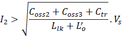
Due to more inductive energy with this leg, capacitors charge/discharge within dead time and then MOSFETs turn-on with ZVS.
The ZVS range can improve with
- Selecting the higher resonant inductance for storing more energy
- Higher dead time (achieves with high resonant inductor)
- Selecting low switch output capacitances
Out of these 3 possibilities, selecting low switch output capacitances is feasible because, increasing the resonant inductance/dead-time reduces the power delivery capability due to more duty cycle loss.
Leave a Reply